Project Summary:
Electro-permanent magnetic clamp (EPMCs) is used to produce large reluctance forces to hold ferromagnetic materials without the need for a continuous power supply. In this project, an EPMC is designed and optimized to generate a reluctance force in the order of 6650 N that can hold a work piece during machining. The design process that was adopted can be broken down into the following steps:
- An FEMM model of the system was created by parsing Matlab with FEMM using OctaveFEMM.
- The FEMM model implemented in MATLAB was optimized using a Genetic Algorithm routine.
- The FEMM results were validated using ANSYS Maxwell.
The reluctance force generated in the “ON” and “OFF” positions were found to be ~6650 N and 17 N respectively.
Optimization constraints:
- The longitudinal cross section of the steel poles (1020 steel) are 50 mm x 50 mm,
- The centers of the poles are 60 mm apart.
- A minimum reluctance force of 1500 lbs (approximately 6650 N) has to be applied on the workpiece in the “ON” position along with a negligible force in “OFF” position.
- The cross sections of the AlNiCo magnets are constrained by the dimensions of the coil bobbins.
- The following parameters were optimized: dimensions of the steel poles and case, the sizes and grades of the PMs (NdFeB and AlNiCo).
Considerations:
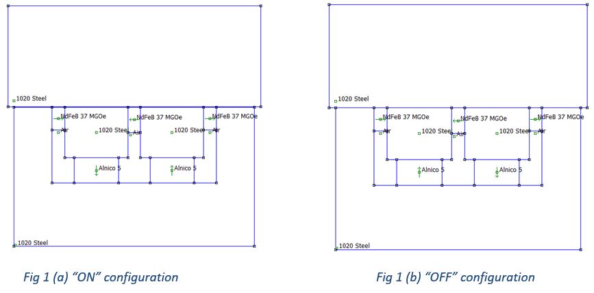
The EPMC employs an electrical excitation impulse to switch between its “ON” and “OFF” configurations. In its “OFF” state, all the flux paths are contained within the EPMC body so that a negligible reluctance force acts on the workpiece. Once the circuit is switched “ON”, the polarities of the AlNiCo PMs are reversed, forcing the flux lines to jump to the work piece, clamping it in place (refer to the image above).
- Only three grades of AlNiCo’s namely AlNiCo 5, 6 and 8 were considered.
- Four grades of NdFeB namely N37, N40, N42, N52 were considered.
- An air gap of 0.1 mm was used between the workpiece and EPMC interface.
- The cost of the permanent magnets were calculated using prices available online.
FEMM simulation with GA:
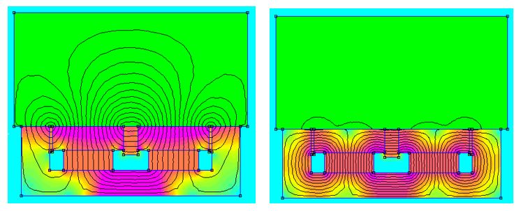
FEMM simulated results showing the magnetic flux lines (a) "ON" position (b) "OFF" position. Note that, in the "OFF" position hardly any magnetic flux lines traverse through though the steel piece.
The dimensions of the magnets and EPMC case were optimized by using a Genetic Algorithm (GA) in combination with OctaveFEMM. Some of the parameters which govern the efficiency of the algorithm include initial population, mutation rate and crossover rate. A randomly generated initial population (size – 100) was used to initiate the algorithm. A mutation rate of 10% and crossover of 50% were considered for the optimization process. The genetic algorithm was run for 20 generations. The cost function associated with the genetic algorithm is defined as follows:
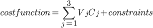
j - NdFeB, AlNiCo, steel
V – respective volumes of materials used
C – cost/volume of respective materials
The constraints were implemented using a penalty parameter that minimizes the difference between the force output (from FEMM) and the desired force of 6650N. However, it should be noted that this cost function merely optimizes the force obtained in the “ON” position and these results are referred to as the Pseudo Optimized GA Results. The design was then optimized iteratively for the “OFF” position using Pseudo Optimized GA result as base dimensions. The new result obtained from this iterative process are referred to as the Iterated GA Results and the “ON/OFF” forces were again simulated using FEMM.
ANSYS Maxwell simulation:
Maxwell simulations are used as a verification tool for the FEMM simulation results. Maxwell provides a 3D simulation environment as opposed to a 2D FEMM simulation. Hence, Maxwell is expected to produce more realistic results compared to FEMM.
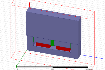
3D Geometry setup for Maxwell
The above figure shows that flux was contained in the case during the “OFF” stage, and the flux jumped into the workpiece once the circuit is switched “ON”. A reluctance force of ~6550 N was observed in the “ON” position, which is very close to the desired value of 6650 N. This 2.5% deviation in force can be attributed to the planar differences in AlNiCo area and that Maxwell takes fringing in all directions into account unlike FEMM. A reluctance force of ~20N was obtained for the “OFF” position, which is negligible and will not influence the functioning of the EPMC. The isometric view of the Maxwell model shows that the AlNiCo does not have the same depth into the page as other components in the EPMC.
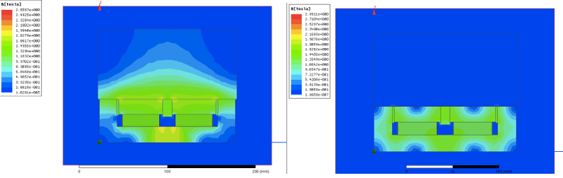
Magnetic flux lines simulated using 3D Maxwell. The left image corresponds to the EPMC "ON" position and the right image corresponds to the EPMC "OFF" position. The results match within ~2.5% deviation with FEMM.