Flexure hinge summary :
My flexure design laser cut out of a FL 301 SS sheet of thickness 0.016" from Rapid Sheet Metal.
- Can be used to join two beam segments.
- Alternative to traditional rotary joint/bearing.
- Useful for operations that does not require full 360
 rotations.
 - No need of maintenance – lubrication.
- Less number of assembled parts.
- Could be used to tune the structural natural frequencies and mode shape by changing the flexure design variables

A flexure hinge serves as a connection or a joint between two structural elements. The flexure hinge could provide an alternative to a rotary bearing, especially in applications where full rotary motions (i.e. complete 360-degree rotations) are not required. Rolling or sliding surfaces are prone to fouling and require periodic maintenance (lubrication). Using a flexure hinge removes the maintenance requirement and reduces the number of assembled parts.
Additionally, using a flexure hinge segment could provide additional tuning capability within a structure. A flexure segment causes an abrupt change in the bending rigidity of the structure that will in turn be reflected in the mode shapes and natural frequencies of the complete structure. At the same time, this segment could be designed to maintain enough stiffness against deformation in other directions such as in-plane bending and out-of-plane torsion to prevent undesired vibrations.
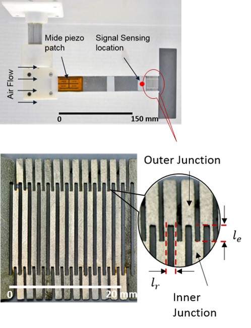
One such usage of the flexure hinge is demonstrated below, in an aeroelastic energy harvesting device. To create an abrupt change in the out-of-plane bending rigidity of the structure, a series of patterned cuts are integrated into the substrate, creating a compliant flexure segment and dividing the structure into a ‘beam segment’ upstream and a ‘flap segment’ downstream. Compared to previous modal convergence flutter energy harvesters, which used a discrete pin or ball-bearing hinge assembly between a beam.
Mathematics behind the hinge design :
Variable definition:
 - number of rigid links
 - length of each rigid links (constant)
 - overall length of flexure struture
 - rotational stiffness of each link
 - tip load
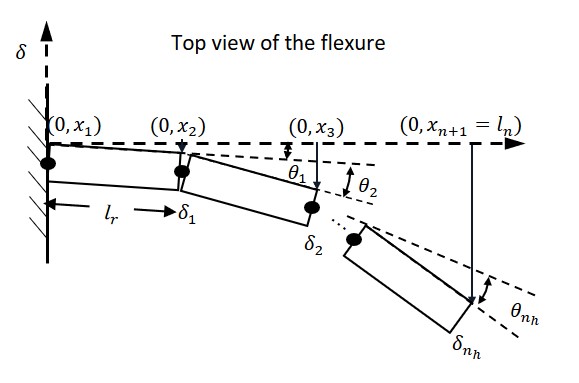
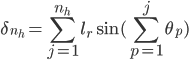
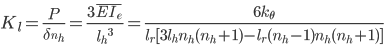
In order to derive the effective bending rigidity, the patterned flexure segment is discretized into rigid links each having an elemental length of . Each of these elemental links are connected to the preceding link with a rotational spring. Figure above shows this arrangement of links and rotational springs cantilevered from a wall and bending due to a load applied to the tip of rigid element. Under these conditions, the tip deflection of the discretized structure undergoing bending is given by
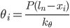
Balancing the moment acting across the tip and root of the  rigid element gives us the torsional rotation of the spring as
Assuming small angles and neglecting the effect of geometric foreshortening under large deflections, the effective linear tip stiffness of the discretized structure is given by  This can be further equated to the linear tip stiffness of an equivalent beam of length and with the same cantilevered boundary conditions
Thus, the effective bending rigidity of the flexure segment,  can now be written as
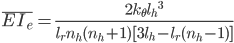
This equation is useful as it relates the geometric properties of the flexure hinge to that of the bending rigidity of this segment, facilitating the tuning of the flexure segment to affect the desired natural frequencies of the entire structure.
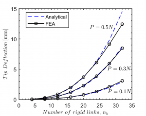
Verification of mathematical model using ANSYS :
Note:
For further details please refer to the publication below:
Chatterjee, P., & Bryant, M. (2015). Structural modelling of a compliant flexure flow energy harvester. Smart Materials and Structures, 24(094007). https://doi.org/10.1088/0964-1726/24/9/094007